
Terminate and wiremap a Leviton Cat 6 data-outlet practice link
Build an isolated two-jack T568B bench link with supported 110 termination, capped QUICKPORT outlets and a checked eight-wire map.
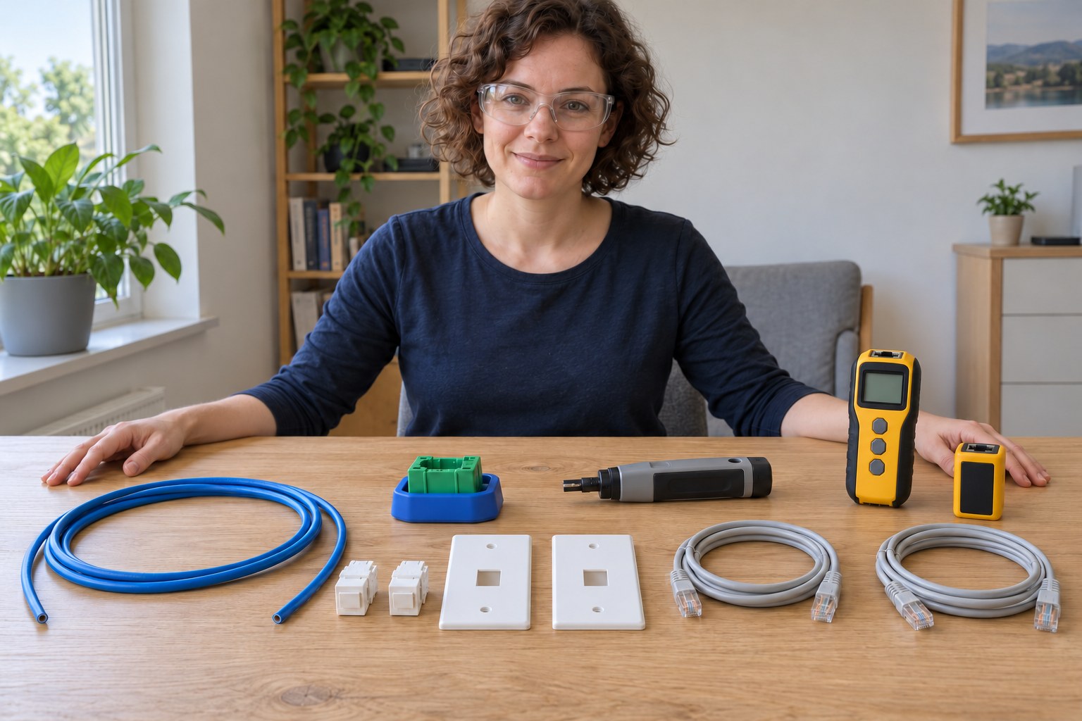
What will you learn?
Build an isolated two-jack T568B bench link with supported 110 termination, capped QUICKPORT outlets and a checked eight-wire map.
Tools
- KleinVDV427-300 with locked110 cutting bladeSearch Amazon Australia ↗
- Compatible jack termination holder such as Leviton47615-PTTSearch Amazon Australia ↗
- Cable-jacket stripperSearch Amazon Australia ↗
- Wire cuttersSearch Amazon Australia ↗
- Klein LAN Scout Jr.2 VDV526-200 with matching remoteSearch Amazon Australia ↗
- Eye protectionSearch Amazon Australia ↗
- RulerSearch Amazon Australia ↗
Materials
- Two matching Leviton 61110-RW6 Cat 6 QUICKPORT jacks and supplied capsSearch Amazon Australia ↗
- Two compatible QUICKPORT platesSearch Amazon Australia ↗
- About 1.2 m of four-pair 23 AWG solid bare-copper U/UTP cable, such as Belden 2412Search Amazon Australia ↗
- Two known-good straight-through RJ45 patch leadsSearch Amazon Australia ↗
- Label for the finished practice linkSearch Amazon Australia ↗
Step by step
Photorealistic illustration · Waey
1. Choose an isolated bench link
Use two matching Leviton 61110-RW6 Cat 6 QUICKPORT jacks with their caps and compatible plates. Prepare about 1.2 metres of four-pair, 23 AWG solid bare-copper U/UTP cable, such as Belden 2412. Keep both ends disconnected from every router, switch, PoE injector and telephone connection throughout. Work indoors on a dry clear table with eye protection. Inspect the cable, jacks, patch leads and tools; replace damaged parts before starting.
Photorealistic illustration · Waey
2. Expose the pairs without nicking them
At the first end, mark about 75 mm, or three inches, from the tip. Carefully remove only the outer jacket with a suitable cable-jacket stripper. Protect the insulation on all eight conductors; if a conductor is nicked, cut back to sound cable and prepare the end again. Trim back any separator or ripcord without cutting the pairs. Keep each coloured conductor twisted with its matching white-striped partner until routing requires separation.
Photorealistic illustration · Waey
3. Follow the jack’s T568B label
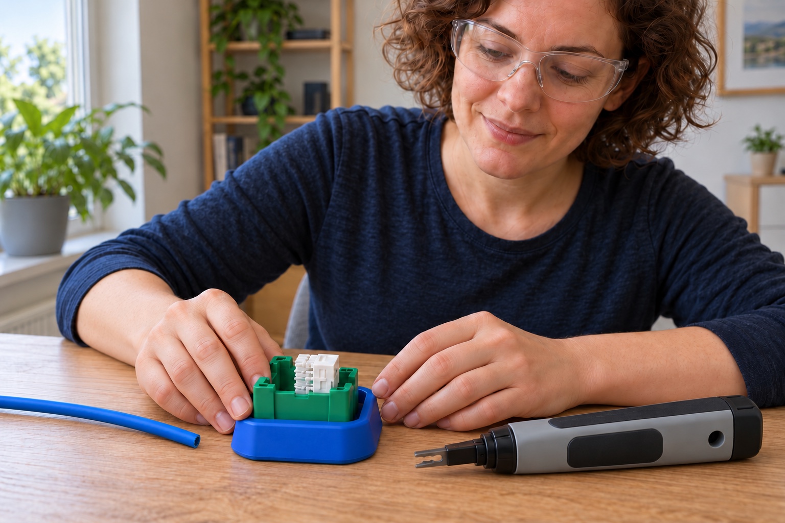
Place the jack securely in a compatible termination holder. Bring the cable to the rear termination field, with the jacket no farther than 3 mm from the jack’s side and enough slack for routing. Read the actual T568B colour legend on that jack and finger-seat each conductor in its matching slot. Keep pair twists within 13 mm of each contact. Where the jack has a two-layer A/B label, leave its T568B top label in place. Do not copy plug pin order into the physical IDC slots.
Photorealistic illustration · Waey
4. Seat and trim with the 110 blade
Fit and lock the 110 cutting blade in the Klein VDV427-300 and select LO impact. Check which side cuts: the blade’s cutting knife aligns with the tool’s marked CUT side. Point that side toward the excess wire outside the jack, away from the cable that must remain connected. Support the holder on the table and keep fingers clear. Hold the blade perpendicular to each contact and press until the tool clicks. Inspect every seated conductor and remove loose cut ends.
Photorealistic illustration · Waey
5. Terminate the other end the same way
Prepare the second end using the same jacket allowance, twist limits and actual T568B jack legend. Seat and trim its eight conductors with the supported 110 tool on LO. Confirm each complete pair remains together: orange on pins 1–2, green on 3–6, blue on 4–5 and brown on 7–8. These are logical pin pairs, not an IDC slot layout. Do not swap to T568A at this end or strip individual conductor insulation.
Photorealistic illustration · Waey
6. Fit the caps and compatible plates
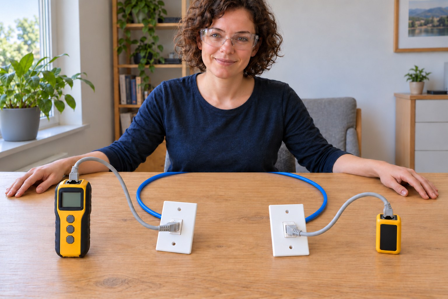
Inspect both termination fields for fully seated wires, untrimmed tails, damaged insulation or loose metal scraps. Fit each supplied dust cap as shown in the jack instructions. Snap each jack into a compatible QUICKPORT plate, following the plate’s UP orientation and the matched insertion diagram. Keep the assembly on the bench; no wall opening or mains box is involved. Leave a loose cable curve so the solid conductors are not sharply bent or pulled against the terminations.
Photorealistic illustration · Waey
7. Connect the wiremap tester and read both rows
With the link still isolated, connect one known-good RJ45 patch lead from the first jack to the top port of a Klein LAN Scout Jr. 2 VDV526-200. Connect a second known-good lead from the other jack to its matching remote. The finished bench cable should remain at least 0.5 metre long for this tester’s split-pair detection. Turn the tester on and press TEST. Require Pass, matching 1–8 rows and no X-Over, Split, Open or Short indication. An unshielded link needs no Shield indication.
Photorealistic illustration · Waey
8. Resolve faults and finish the bench assembly
If Voltage appears, disconnect immediately and identify the unintended powered connection before further work. For a wiring fault, turn the tester off and remove the patch leads before inspecting the reported pins against both jack labels. Rule out the patch leads by testing them separately with the main tester and remote. Replace a damaged jack or cable end rather than forcing its contacts; repeat the complete wiremap check after correction. Label a passing link T568B bench practice. This verifies wiring, not Cat 6 bandwidth or installed-network certification.
Video demonstrations
eXtreme Connector Termination
Manufacturer demonstration of the EXTREME connector family: holder at 0:45, B-wiring context at 1:30, conductor routing at 1:55 and individual punchdown at 2:20. The demonstrated red jack and tool differ from the selected white 61110-RW6 and Klein tool; use their matched current manuals for dimensions, labels and blade settings. Selected frames reviewed, not the whole audiovisual sequence.
Leviton · English automatic track advertised; complete speech not assessed
Watch on YouTube ↗LAN Scout Jr. 2 Cable Tester (VDV526-200)
Manufacturer product demonstration; 0:30 shows the matched LAN Scout Jr. 2 screen and three-button interface. Rack environment does not establish disconnected cabling. Use the current manual for isolated two-jack testing, remote connections and result interpretation. English on-screen labels; speech language unverified. The advertised Spanish automatic caption track is not an Arabic translation.
Klein Tools · Spanish automatic track advertised despite English screen titles; speech language not verified
Watch on YouTube ↗Final checks
Both jacks T568B, twists maintained, caps fitted, no scraps or damage, isolated two-patch-lead path, minimum cable length checked, matching 1–8 wiremap and no fault/crossover warning.
Where to find supplies
Only the matched 61110-RW6 / 110 blade / LAN Scout Jr. 2 bench procedure is covered. Other jack labels, tool heads and tester limits require their own manuals. No active port, PoE, telephone, shielded cable, building installation or bandwidth certification.
Sources
Leviton current jack instructions, 2025 ↗
Leviton current jack specification, May 2025 ↗
Klein 110 punchdown tool instructions ↗
Klein LAN Scout Jr. 2 manual ↗
Belden 2412 manufacturer product specification, revision 0.790, 20 February 2026 ↗
Original illustrations for this guide. The jack image shows preparation before wire placement; follow the actual jack labels and tool instructions for termination.