
Prepare wires, build and troubleshoot a switched LED circuit
Learn wire cutting and stripping, breadboard layout, resistor reasoning, switch continuity and DC-voltage diagnosis while building a complete battery-only practice circuit.
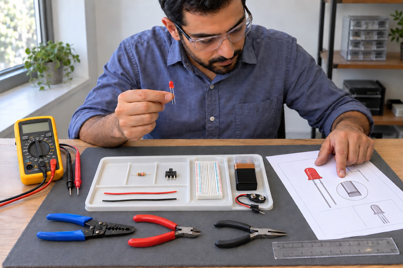
What will you learn?
Learn wire cutting and stripping, breadboard layout, resistor reasoning, switch continuity and DC-voltage diagnosis while building a complete battery-only practice circuit. The photographs show tool use and component details; use the written connection plan and your actual board’s labels for assembly. Displayed readings are illustrations. The credited real LED photograph shows an illuminated component, not proof of this complete circuit or a tested prototype.
Tools
- Wire cutter and manual gauge stripper explicitly suitable for 22 AWG solid copper wireSearch Amazon Egypt ↗
- Smooth-jaw pliers, small ruler and offcut container; eye protectionSearch Amazon Egypt ↗
- Digital multimeter and intact guarded probes, with its manual and short breadboard test pinsSearch Amazon Egypt ↗
Materials
- 400-point solderless breadboard with confirmed row connections; insulated 22 AWG solid-core red and black wireSearch Amazon Egypt ↗
- One datasheet-identified red 5 mm indicator LED, such as Kingbright WP7113ID; one 1 kΩ ¼ W resistor of known toleranceSearch Amazon Egypt ↗
- One three-pin 2.54 mm-pitch breadboard-compatible SPDT slide switch with verified common pinSearch Amazon Egypt ↗
- One 9 V alkaline battery, protective terminal cap and matching clip with proper breadboard-ready male pinsSearch Amazon Egypt ↗
Step by step
Photorealistic illustration · Waey
1. Select known components and calculate the resistor margin
Use a red two-lead indicator LED with an available datasheet, a 1 kΩ, ¼ W resistor and only a 9 V alkaline battery. Confirm that the LED permits the intended current and identify its anode and cathode from its actual markings and drawing before applying power. For an illustrative 9 V supply and 2 V LED drop, current is (9−2)/1000 = 7 mA and resistor dissipation is about 0.049 W. Actual battery voltage, LED drop and tolerances vary. A resistor limits current; it does not make incorrect polarity harmless.
Photorealistic illustration · Waey
2. Set up the meter and verify the loose resistor
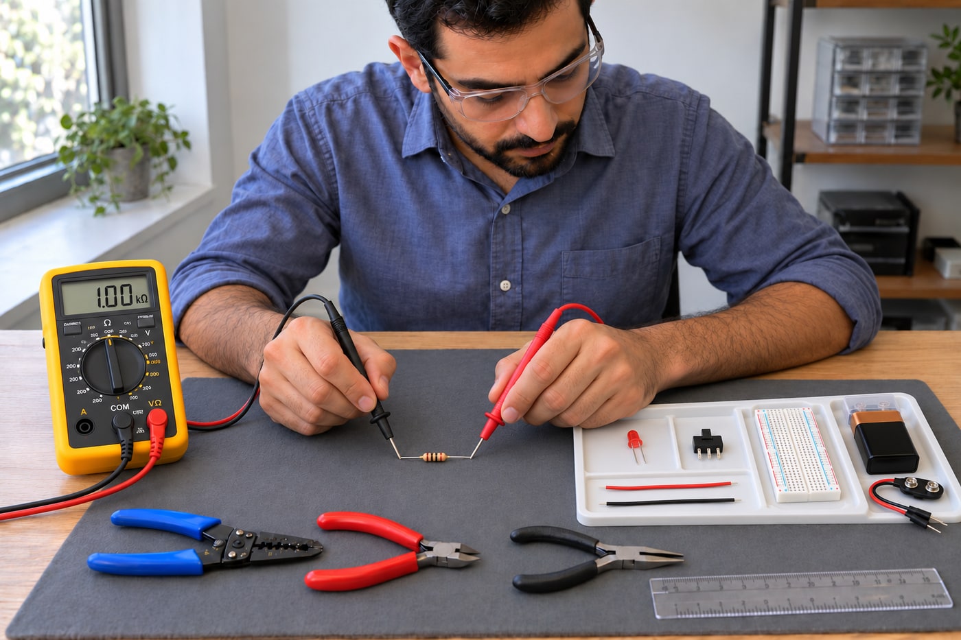
Inspect the meter and leads and read the manual for its controls. Put the black lead in COM and the red lead in the V/Ω input, leaving current inputs unused. With the battery physically disconnected, select resistance and measure the loose resistor across its two leads, without touching exposed probe metal. Expect approximately 1 kΩ within its tolerance, not a continuity beep. A wrong range or poor contact can imitate a fault. Do not measure resistance on a powered circuit, and never use an A or mA input across the battery.
Photorealistic illustration · Waey
3. Map the breadboard and prove the switch contacts unpowered
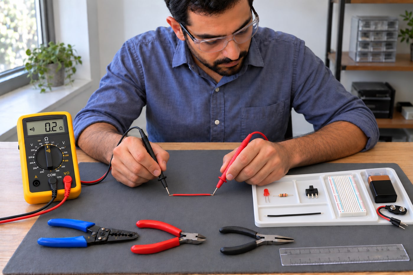
With the battery absent, first confirm continuity response on a known short jumper and an open circuit. Then check the five connected holes in each row; the centre gap separates a–e from f–j. This layout uses only a–e, leaving power rails unused. Use inserted test pins or suitable fine tips without forcing sockets. Check the loose SPDT switch: its middle common connects to one outer pin in each position. Identify the position joining the intended input and output rather than guessing from slider direction. The jumper photograph illustrates the preliminary meter check.
Photorealistic illustration · Waey
4. Measure and cut the jumper wires safely
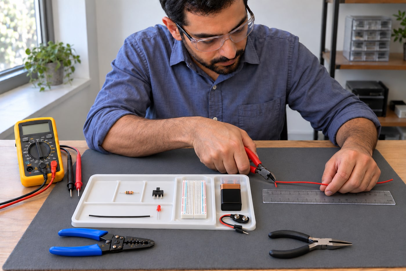
Choose insulated 22 AWG solid-core hookup wire compatible with the breadboard and a cutter rated for that wire. Plan a red jumper between d5 and a11 and a black jumper between a16 and d20, allowing for neat bends and insertion at both ends. Cut a trial length away from the disconnected battery and components, controlling the offcut so it cannot fly into an eye or remain on the board. Wear eye protection. Wire colour is an organisational choice in this DC exercise; it does not establish conductor function in household wiring.
Photorealistic illustration · Waey
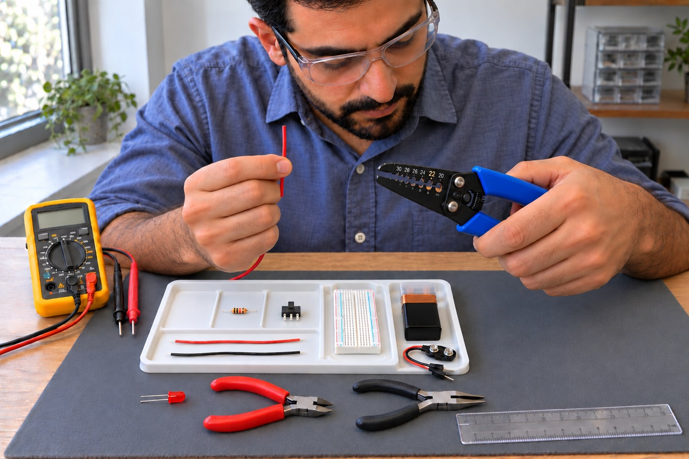
5. Strip the insulation with the matching gauge notch
Match the stripper’s solid-wire gauge marking to the actual wire; AWG numbers and metric conductor areas are not interchangeable labels. Practice on an offcut before preparing the final jumpers. Remove only the length needed for secure insertion, commonly around 5–10 mm for these breadboard wires, adjusted to the actual socket and layout. Follow the tool’s closing and pulling method, keeping the other hand behind the cutting area. A notch that is too small can score the copper; one that is too large may not remove insulation. Do not substitute a knife.
Photorealistic illustration · Waey
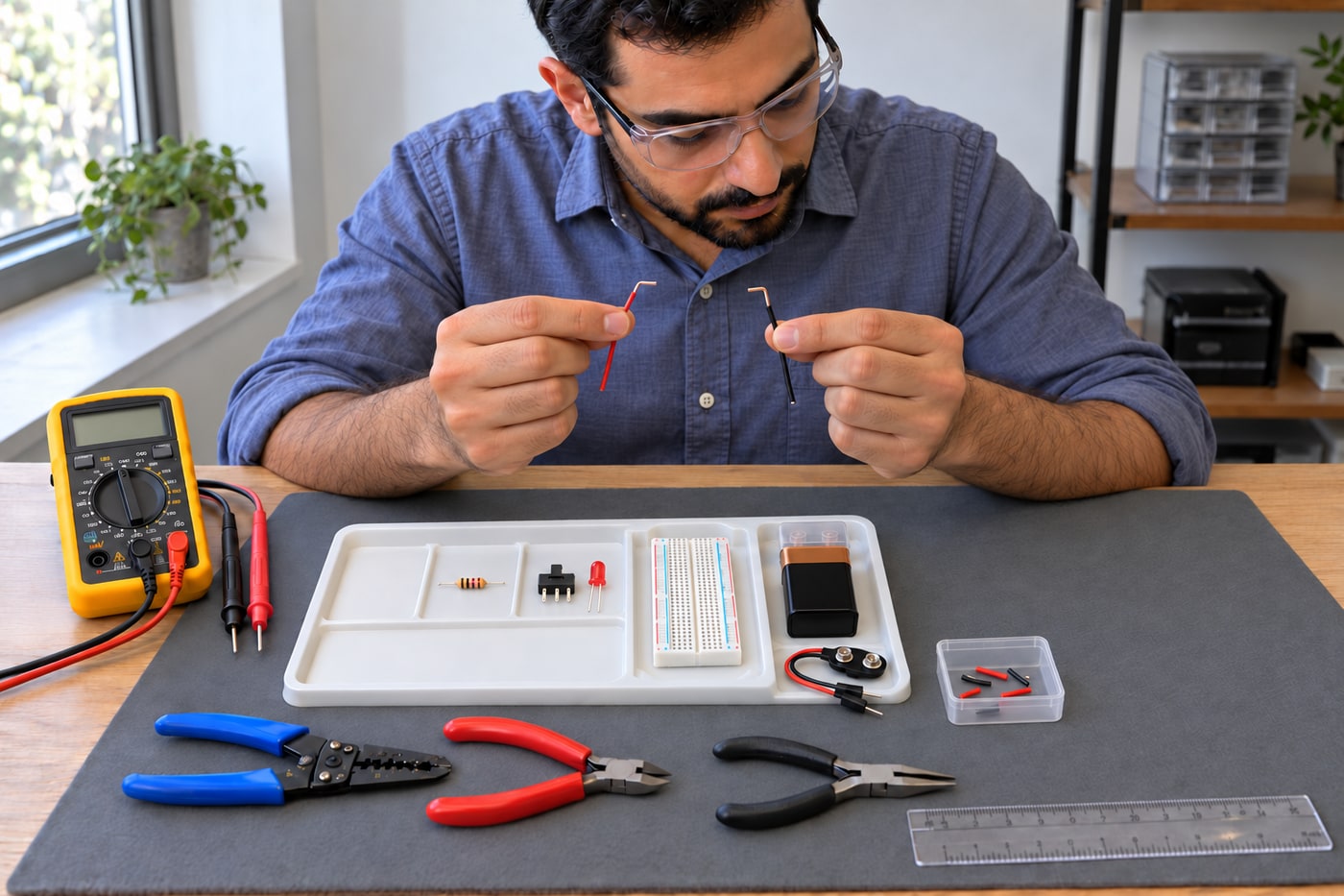
6. Inspect the copper and form supported bends
Examine each stripped end in good light for a nick, reduced diameter, a sharp hook or cracked insulation. Cut away a damaged end and strip it again; repeatedly bending a scored conductor can make it break inside a socket. Form gentle right-angle insertion legs with suitable smooth-jaw pliers, supporting the wire rather than levering against the insulation. Seat a trial end without excessive force and keep exposed copper short enough to avoid adjacent contacts. Collect every metal offcut. Use a commercial battery clip with proper breadboard-ready pins instead of pushing loose stranded tails into holes.
Photorealistic illustration · Waey
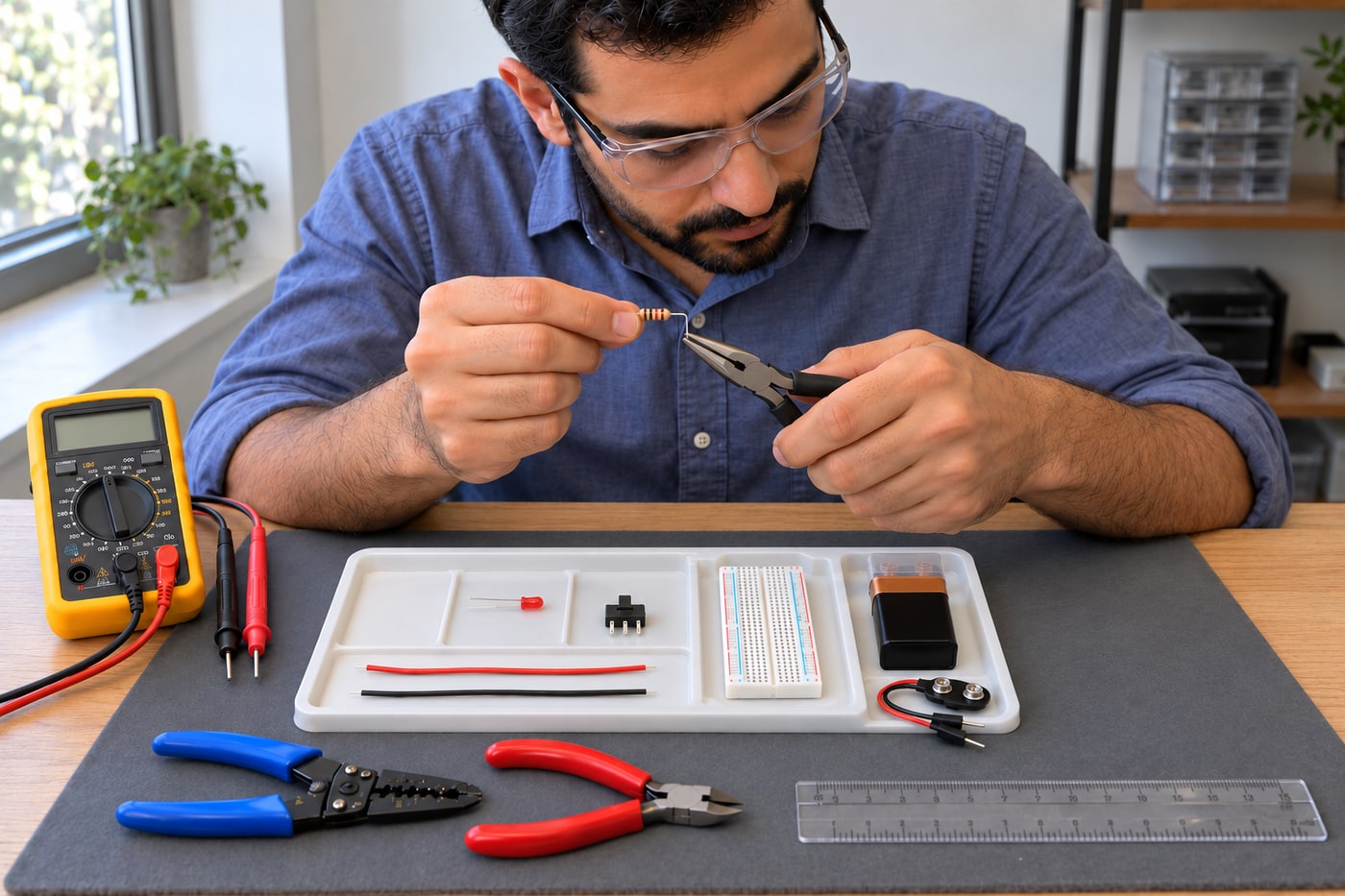
7. Build the resistor and LED section with power disconnected
Orient the board so its printed row and column labels are readable, then verify this example against its actual internal connections. Fit the resistor between d10 and d15. Fit the LED anode in e15 and cathode in e16, using the datasheet to confirm polarity before inserting it. The resistor and LED share row 15, while the two LED legs occupy different rows. Gently form component leads without pulling against the body or leaving crossed bare legs. Never put both LED leads into one connected row, and never bypass the series resistor.
Photorealistic illustration · Waey
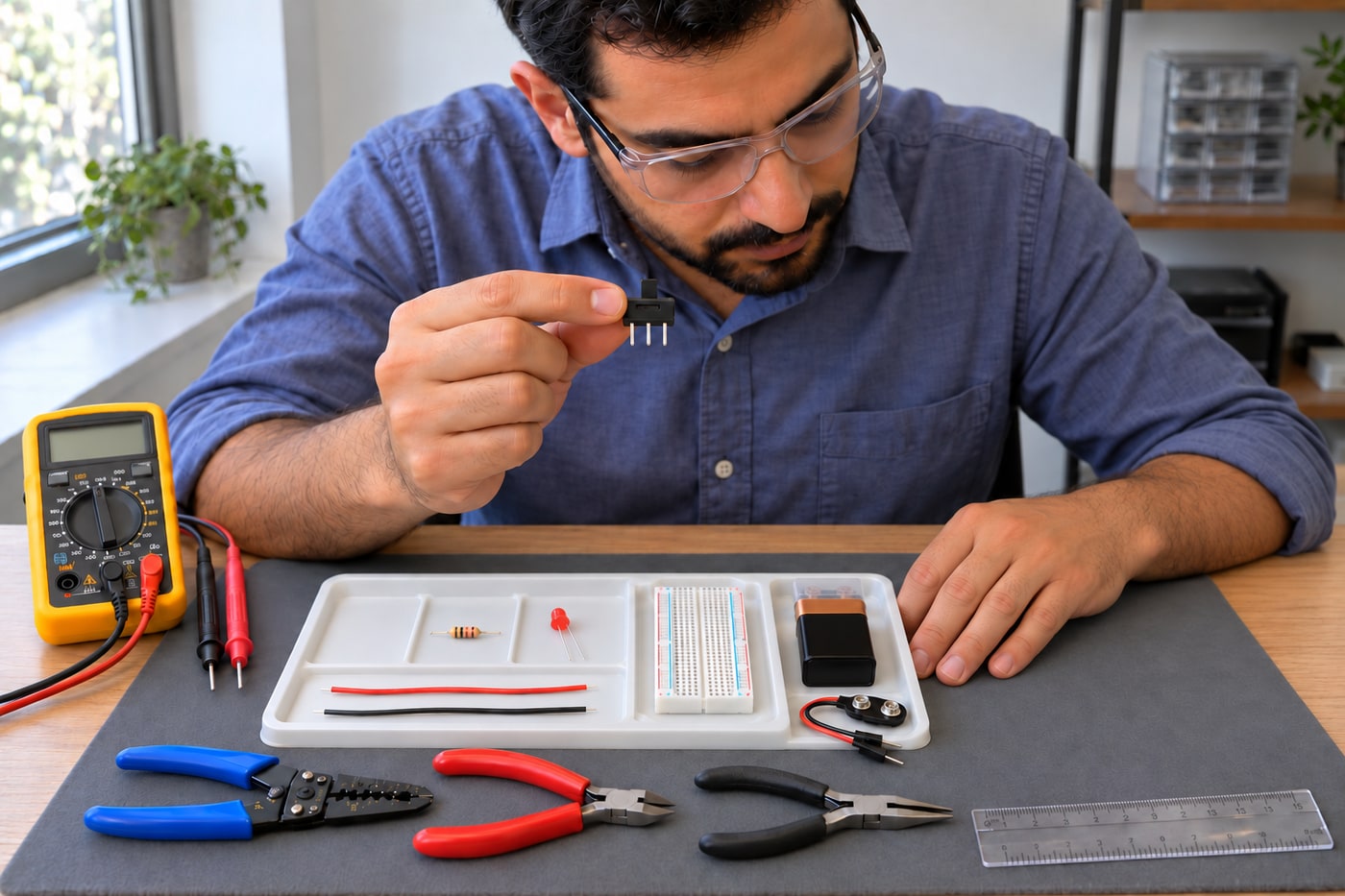
8. Add the switch and complete the disconnected wiring
Use a breadboard-compatible three-pin SPDT switch with 2.54 mm pitch. Place its pins in b10, b11 and b12, with the verified middle common in row 11. Put the clip’s red pin in a5 and the prepared red jumper from d5 to a11. Put the black jumper from a16 to d20 and the clip’s black pin in a20; leave row 12 otherwise unused. Select the position that disconnects rows 11 and 10. The clip remains detached from the battery throughout assembly. Other boards or switches require a revised, checked layout.
Photorealistic illustration · Waey
9. Trace the complete path before connecting the battery
With the battery still absent, trace positive clip → red jumper → switch common → selected outer contact → resistor → LED anode → cathode → black jumper → negative clip. Check row numbers, LED orientation and bare-wire clearance. Use continuity only on individual jumpers and the switch path, not as a pass/fail test across the whole resistor-and-LED circuit. Its resistance and diode behaviour may prevent a beep even when correctly assembled. Check that no wire directly bridges positive and negative. Return the meter to DC voltage before any powered check, leaving red in V/Ω.
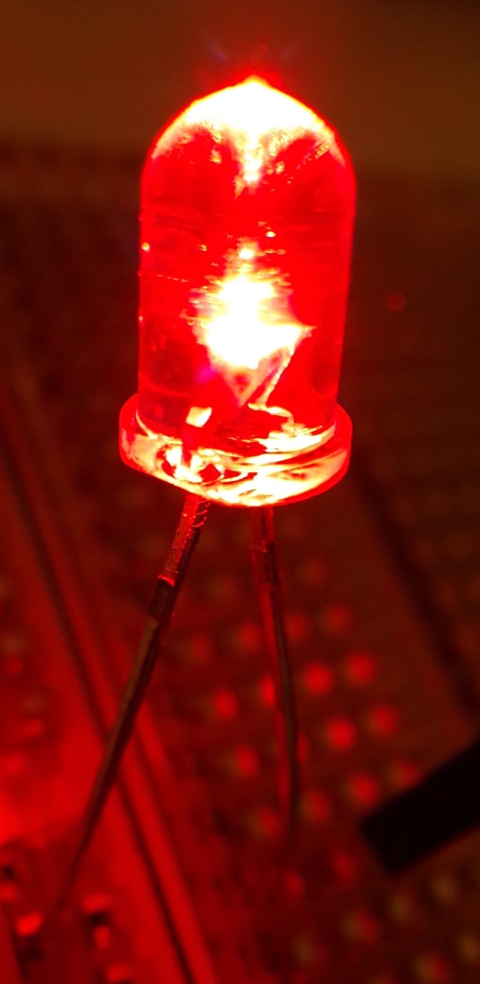
Trougnouf · CC BY 4.0 · Resized and JPEG re-encoded. Illuminated LED reference; supply, resistor and switch are outside the photograph.
10. Power the circuit and test both switch positions
After the disconnected checks pass, keep the switch in its open position and attach the clip to the 9 V alkaline battery with correct polarity. Support the battery so it cannot roll onto tools or pull the wiring. Move the switch to the verified closed position; the LED should light steadily, then go out when opened. Disconnect immediately if anything warms, smells unusual or behaves unexpectedly. Do not deliberately reverse the LED to experiment: its reverse-voltage rating can be lower than this battery voltage. Make every wiring correction with the battery physically removed.
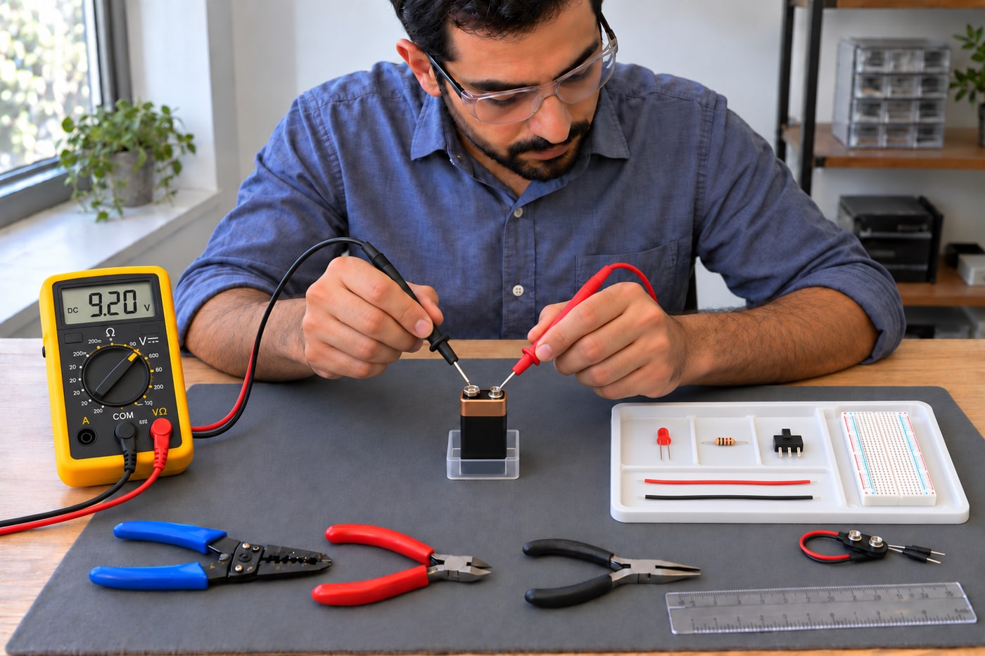
Photorealistic illustration · Waey
11. Use DC voltage to locate a fault without current mode
Check that the meter is in DC volts with black in COM and red in V/Ω; select an appropriate range above the battery voltage if required. Use accessible short test pins and keep probe tips separated. Across the powered supply nodes c5 and c20, red to positive, expect the actual battery voltage. With the switch closed, compare the voltage across the resistor at c10/c15 and LED at c15/c16. A resistor drop of 7 V implies about 7 mA through 1 kΩ, avoiding a series current test. Disconnect before moving or replacing components.
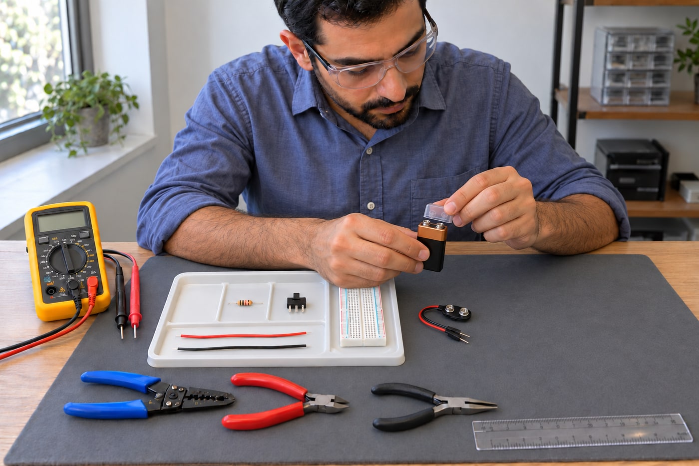
Photorealistic illustration · Waey
12. Record the checks and leave the practice board safe
If the LED stays dark, disconnect and revisit one cause at a time: battery condition, a loose pin, wrong row, open switch, incorrect resistor or uncertain LED polarity. Do not replace the resistor with a wire or keep cycling power through a suspected fault. Record the final connection map and measured values so the exercise teaches diagnosis rather than trial and error. Finish by detaching the battery, protecting its terminals from metal contact and storing it separately. Switch off the meter, collect offcuts and retain the board as a clearly labelled battery-only practice circuit.
Video demonstrations
How to Use a Breadboard
Breadboard connections, an actual LED build and common wiring mistakes. Its 2×AA/47Ω example is different: never copy that resistor into our 9 V circuit.
Science Buddies · English
Watch on YouTube ↗LED Basics
A complementary explanation and demonstration of LED polarity, forward voltage and current limiting. Check the actual LED datasheet; this guide does not use an adjustable supply or reverse-polarity experiment.
Afrotechmods · English
Watch on YouTube ↗Easy LED Circuit Tutorial
A complete LED/resistor/switch build with a different battery arrangement and soldered wiring. Use it for the series-circuit reasoning; this guide stays solderless, uses 9 V and its own checked resistor.
Becky Stern · English
Watch on YouTube ↗How to Use a Multimeter
Useful meter demonstrations for resistance, continuity and voltage. This task uses only disconnected resistance/continuity and powered low-voltage DC volts, never the current-input or mains demonstrations.
SparkFun Electronics · English
Watch on YouTube ↗How To Strip a Wire
A manual gauge-stripper demonstration. Match the actual wire and follow the tool maker’s method rather than guessing by feel or copying a twisting action that may score solid copper.
Howcast · English
Watch on YouTube ↗Final checks
Known resistor and LED ratings; correct rows and series path; unpowered checks; switch controls the LED; sensible DC readings; no heat or bare-wire bridge; battery removed for storage.
Sources
Adafruit: breadboard groups and solid-core jumper preparation ↗
Science Buddies: breadboard connections, LED build and mistakes ↗
SparkFun: matching wire, cutter and stripper; conductor inspection ↗
Kingbright WP7113ID: current 2026 component drawing and limits ↗
Adafruit: 2.54 mm SPDT switch and common contact ↗
Fluke: continuity only without voltage present ↗