
Test a loose blade fuse with a Fluke 101
Check an already loose automotive blade fuse with the Fluke 101, verify the meter before and after, and record a clear result.
What will you learn?
Check an already loose automotive blade fuse with the Fluke 101, verify the meter before and after, and record a clear result.
Tools
- Matched Fluke101 with intact compatible test leads and manualSearch Amazon Spain ↗
- Pen for recording the resultView at Carrefour España (Bic Cristal Original pens) ↗Search Amazon Spain ↗
Materials
- Already loose identified low-voltage automotive blade fuseSearch Amazon Spain ↗
- Known intact loose control fuse of the same familySearch Amazon Spain ↗
- Labels or separate small containersView at RETIF España (white handwritten labels) ↗Search Amazon Spain ↗
Step by step
Photorealistic illustration · Waey
1. Choose an already loose low-voltage fuse
Use a clearly identified low-voltage automotive blade fuse already removed from all equipment, plus a known intact control fuse. Keep the bench dry and clear of batteries, chargers and powered circuits. Read the fuse markings and packaging; do not identify its rating by colour alone. This is a bench continuity check, not instructions to remove a fuse from a vehicle, household plug or fuseboard. Set aside cracked, scorched or corroded parts rather than returning them to service.
Photorealistic illustration · Waey
2. Inspect and set up the Fluke 101
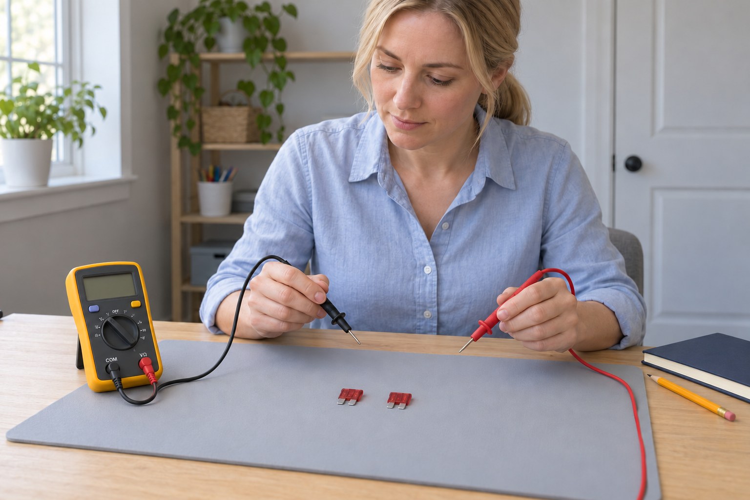
Inspect the meter case, sockets, lead insulation and probe guards. Stop for damage, a low-battery warning or unreliable operation. With the selector off, seat the black lead in COM first, then the red lead in the voltage/resistance input. Select the resistance position and press the yellow button once to enter continuity mode, following the actual Fluke 101 markings. Keep HOLD off and your fingers behind the guards; other meters may select continuity differently.
Photorealistic illustration · Waey
3. Check open and touching probes first
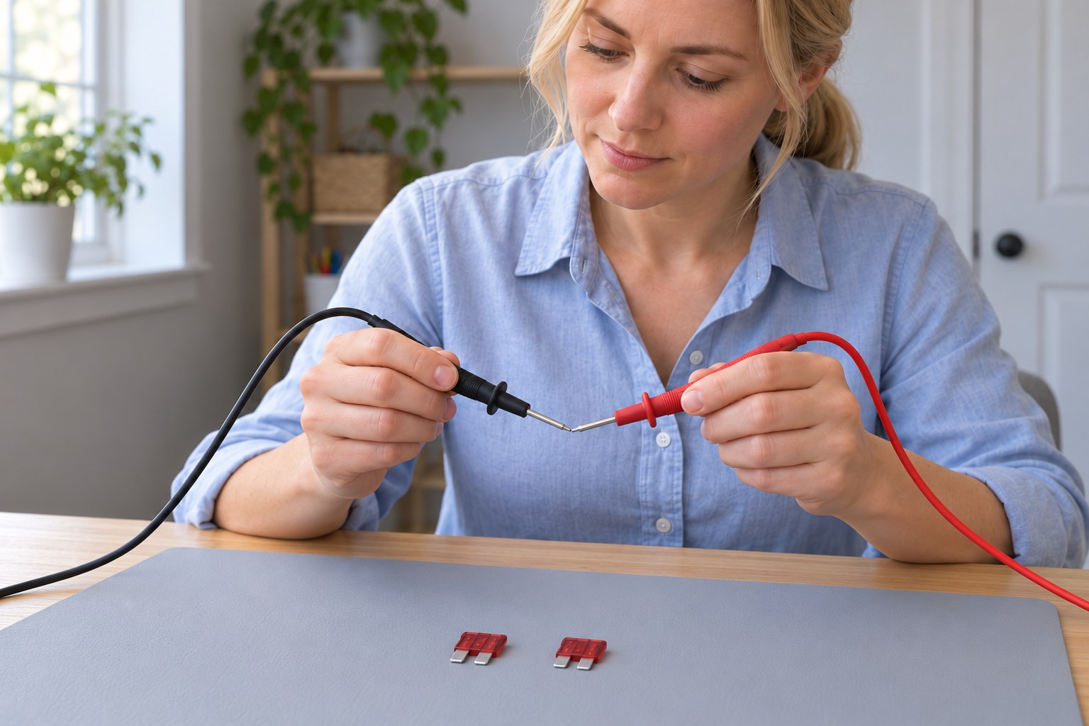
Keep the probe tips apart: the meter should indicate an open path without a continuous tone. Then touch the clean tips together. Confirm a steady tone and low resistance, noting this lead-contact reading as your comparison. Separate them again and check that the open indication returns. Test the known intact loose control fuse across its two blades as well. If these checks fail or fluctuate, stop and resolve the meter, lead or contact problem before judging the suspect fuse.
Photorealistic illustration · Waey
4. Touch one probe to each separate blade
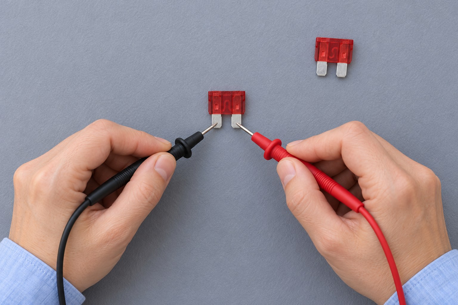
Place the suspect fuse on the dry nonconductive bench where it cannot roll or slide. Hold the insulated probes and place one tip firmly on each of its two metal blades. Keep the tips separate so they cannot touch each other and bypass the fuse. Avoid touching both blades with your fingers. Read the display and note the tone while maintaining steady contact; a momentary slip is not a reliable open-fuse result.
Photorealistic illustration · Waey
5. Interpret the reading without overclaiming
A steady low reading close to your lead-contact and intact-control readings supports continuity through the fuse. A stable open indication with sound contacts indicates an open element. The Fluke 101 beeps below 70 ohms, so a tone alone does not certify a healthy low-resistance fuse: treat high, unstable or ambiguous readings as unresolved. Continuity cannot verify the fuse’s current rating, time characteristic or performance under load, or explain why it opened.
Photorealistic illustration · Waey
6. Recheck, label and put the meter away
Repeat the probe-touch and known-control checks after testing the suspect fuse. If the controls now fail, discard your conclusion and troubleshoot before retesting. Record the fuse markings and result as continuous, open or unresolved, keeping questionable parts separate. Turn the meter off, remove the red lead before the black and store them without sharp bends. Never bridge a fuse or choose a higher rating; any later replacement must match the equipment specification and its fault must be addressed.
Video demonstrations
Fluke 101 For Beginners, Hobbyists, DIYers, Builders & Home Owners
Actual matched101 continuity chapter sampled at8:30 for OL/open display and8:55 for low display;3:00 only body/control identification. Restrict viewing to8:08–9:42 continuity segment. Later AC mains, internal teardown and other functions are outside this loose-fuse guide. No full audiovisual review or audible-beep verification; exact selection/70ohm threshold comes from the101manual.
John Salt · English automatic caption track listed; full speech not assessed
Watch on YouTube ↗How to Test Car Fuses With a Multimeter - Continuity Check
Actual0:40 loose-blade-fuse group and0:55 open-element close-up reviewed for blade/body identification and why appearance alone is insufficient. Uses Fluke115, whose jack layout/function selection are different from101.0:30 shows115open display only; installed-box scenes1:20/3:40 excluded. Follow only already-loose bench scope here, not vehicle removal or in-circuit testing. No full audiovisual review or fuse-current/load certification.
Revive My Ride · English automatic caption track listed among multilingual tracks; full speech not assessed
Watch on YouTube ↗Final checks
Open/short probe controls and intact control fuse pass before and after; steady separate blade contacts; result recorded without equating beep with rated performance.
Where to find supplies
Fluke101 isolated loose blade-fuse continuity only. Other meter selection sequences/thresholds, installed-fuse diagnosis, current tests, mains work and replacement installation are outside this procedure.
Sources
Fluke101 user manual revision0100, actual safety/terminals/continuity figures PDF7,8,11,16,17 ↗
Littelfuse ATOF287 32V DC blade-fuse manufacturer datasheet ↗
Three original generated contexts individually and as final JPEG sequence reviewed across six steps: corrected two-input blank/off preparation, probe-tip contact control and overhead separate metal blade contacts. Same white blonde woman/pale-blue shirt/dry grey mat/red loose blade fuses and guarded probes. Three rejected candidates retained privately: invented third input and two ambiguous blade-root/housing contacts. Exact101 dial positions/symbols, active mode, display/tone, contact resistance, fuse ratings, dimensions and performance are not image proof; actual manual and physical controls govern. No power sources, installed circuits, hand bridge, extra current jack or fuse bypass in selected scenes. No manufacturer/video-image generation inputs.