
Build and fit a removable wooden floor-vent insert
Build a fitted plywood-backed wooden insert for an approved compatible framed floor vent, from measured layout and cutting through attachment and operational checks.
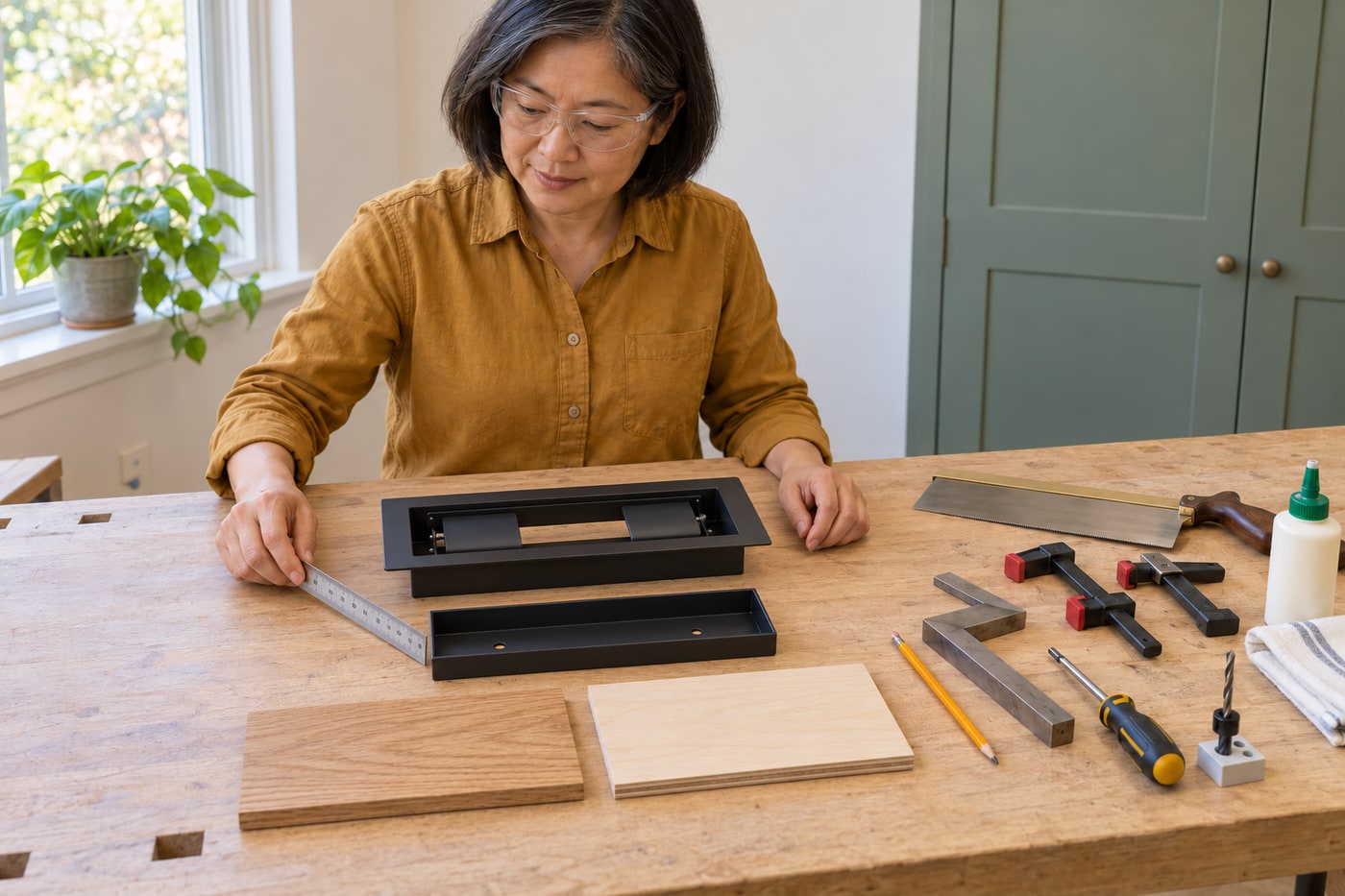
What will you learn?
Build a fitted plywood-backed wooden insert for an approved compatible framed floor vent, from measured layout and cutting through attachment and operational checks.
Tools
- Ruler, square, pencil and thickness gaugeSearch Amazon Ireland ↗
- Stable bench, suitable hand saw and clamps with protective caulsSearch Amazon Ireland ↗
- Eye protection and assessed dust controlsSearch Amazon Ireland ↗
- Glue spreader and cleanup clothSearch Amazon Ireland ↗
- Depth-limited drill bit and matching hand screwdriverSearch Amazon Ireland ↗
Materials
- Matched Fittes Framed Floor Vent Luxe with approved through-hole tray methodSearch Amazon Ireland ↗
- Known sound bare-backed wooden flooring offcut and flat plywood backingSearch Amazon Ireland ↗
- Titebond III for the wood-to-wood joint onlyView at Frank Clark Ireland (Titebond III 946ml) ↗Search Amazon Ireland ↗
- Matched screws of verified safe engagementSearch Amazon Ireland ↗
- Temporary opening guard and surface protectionSearch Amazon Ireland ↗
Step by step
Photorealistic illustration · Waey
1. Confirm the model and installation are suitable
Use this project only for a known Fittes Framed Floor Vent [Luxe] whose actual tray supports the maker’s plywood-backed, through-hole attachment method. Confirm the existing system and location are approved for that exact vent, including expected traffic and airflow. Exclude walkways or high-traffic locations unless this exact model has explicit approval for them. A nominal duct size does not establish capacity: the current 4-by-10-inch Luxe specification lists only 8.4 square inches of open area. Stop for damaged flooring, an unstable duct boot, unknown old materials or unresolved ventilation problems. Do not enlarge the floor or alter ducts.
Photorealistic illustration · Waey
2. Shut down, remove and measure safely
Follow the HVAC equipment’s shutdown instructions before removing the tray or register. Keep people and pets away and guard the temporary floor opening; never leave it exposed while working elsewhere. Lift the removable components without levering against finished flooring. Record the actual body, tray, clear opening and available depth, preserving the original damper setting. Use the exact current dimension sheet as a cross-check, not a substitute for measuring the parts. Stop if the body lacks continuous sound support or cannot be removed safely.
Photorealistic illustration · Waey
3. Plan the insert and its backing
Choose a known, sound, dry flooring offcut with a clean bare-wood bonding face and flat plywood backing. Exclude unknown composites, oily or treated stock and prefinished bonding faces unless separately approved. Lay out the insert to fit the actual tray without binding its side walls or covering the air channel. Build up the backing so the finished face aligns with the tray rim as the maker describes. Include the real glue line and fastening depth; do not blindly copy another size’s dimensions or use adhesive as a thick filler.
Photorealistic illustration · Waey
4. Cut and trial-fit the components
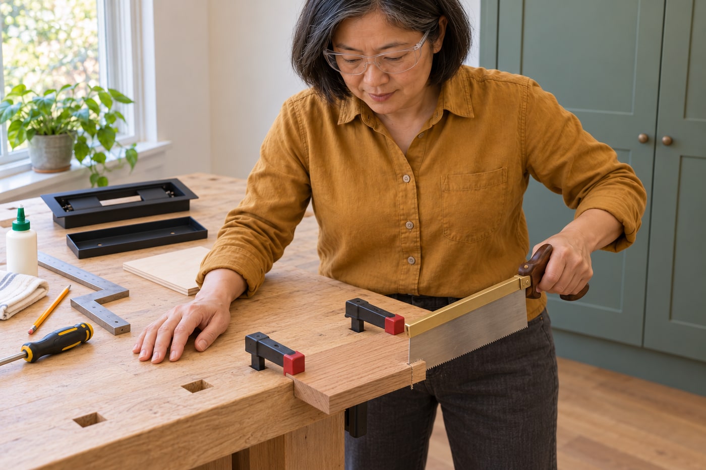
Mark the flooring and backing clearly, accounting for the saw kerf and keeping the visible grain direction appropriate. Support each piece on a stable bench and clamp it securely with the cut beyond the bench edge and hands clear of the blade path. Use a suitable sharp hand saw and eye protection; control and collect cutting dust. Trim gradually, then remove sharp splinters without rounding the visible fit excessively. Trial-fit both dry components in the tray. They must sit flat without force, rocking or interference with removal.

Photorealistic illustration · Waey
5. Bond the wood layers and allow curing
Use matched Titebond III only between clean, close-fitting bare wood and plywood, following its actual label and safety instructions. This is a decorative insert assembly, not a structural floor repair or a new load rating for the vent. Spread an even film, align the layers and clamp with flat protective cauls so pressure does not bow them. Remove wet squeeze-out without spreading it onto the visible finish. The maker advises leaving new joints unstressed for at least 24 hours; actual conditions and label instructions govern. Keep glue away from the metal tray.
Photorealistic illustration · Waey
6. Secure through the existing tray holes
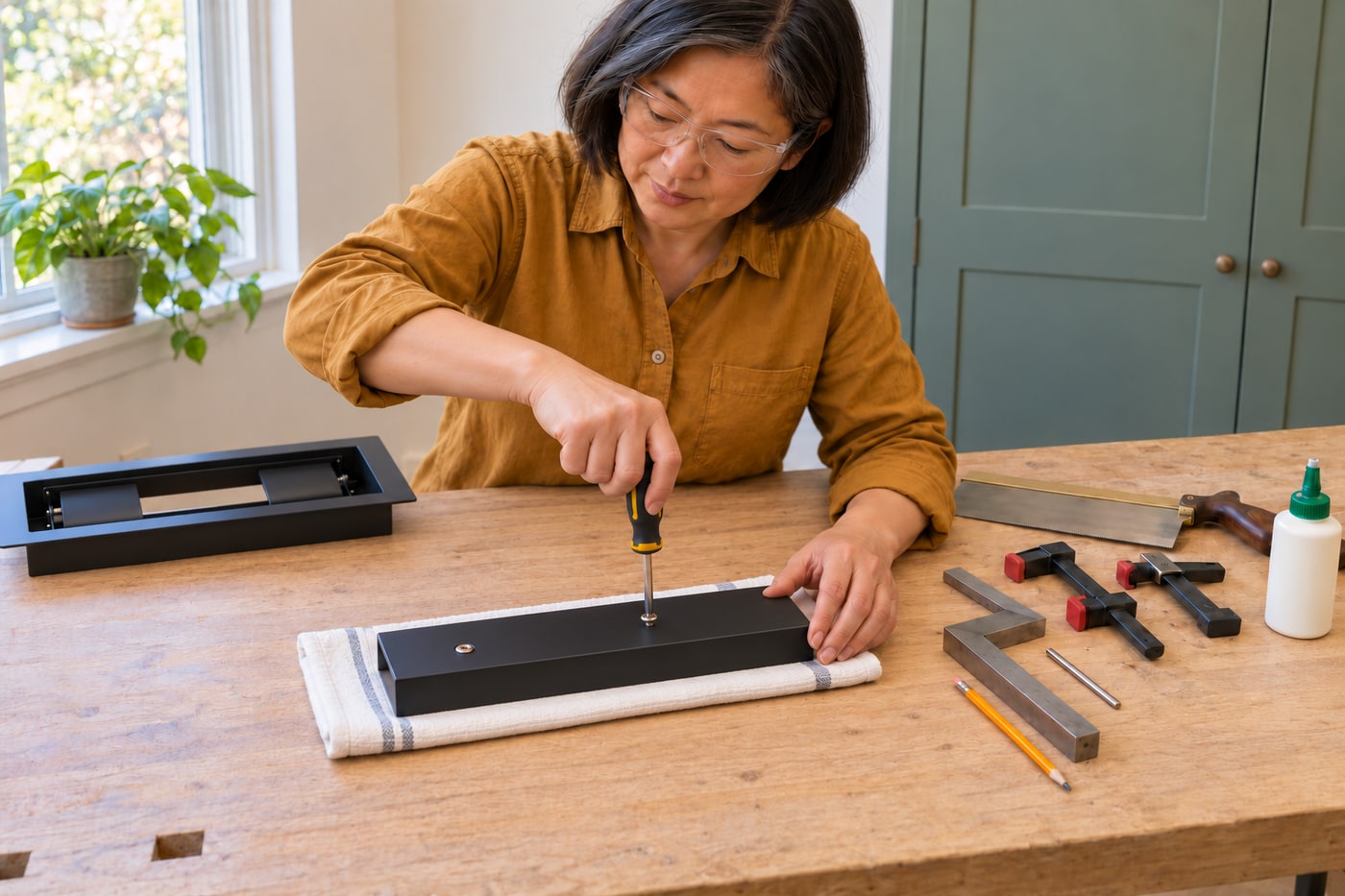
After the wooden assembly has cured, position it accurately in the tray. Use only the maker’s existing attachment holes and appropriate screws into the plywood backing. Establish the actual screw engagement and pilot depth before drilling: the tip must remain within the backing and never reach the finished face. Support the work, use a depth stop and keep hands clear. Tighten carefully with a hand screwdriver until secure without crushing the plywood or distorting the tray. Stop for stripped holes, split backing or a fastening arrangement not supported by the matched product.
Photorealistic illustration · Waey
7. Reassemble without obstructing the channel
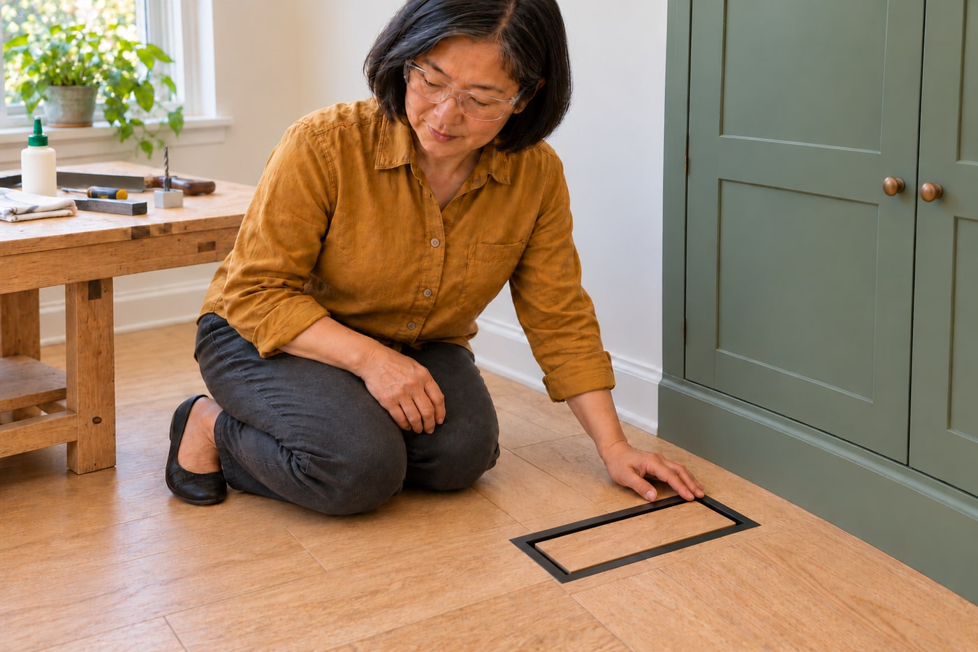
Inspect the assembly for a flush, firmly retained insert and undamaged tray edges. Remove all debris from the work area and accessible register surfaces without pushing it deeper into the duct. Replace the sound body on its original support and refit the tray using the exact model’s sliding or seating action. Keep its perimeter air channel, damper movement and future removal unobstructed. Do not use the insert as a platform or infer a traffic rating from a successful fit. Do not force screws into the floor or improvise support.
Photorealistic illustration · Waey
8. Restore operation and record the result
Once the opening is safely covered and the assembly passes its mechanical checks, restore the HVAC system according to its instructions. Check that the tray remains seated, the intended air path is clear and no new rattling, vibration or whistling appears. Retain the documented damper position unless a competent system assessment calls for adjustment. Feeling air at the vent does not prove required airflow or system balance. Stop and investigate unexpected performance. Record the model, insert construction, fastening details and completion date, and keep the tray removable for maintenance.
Video demonstrations
How to Install a Fittes Framed Floor Vent [Luxe]
Original Framed Luxe installation; floor-only current written instructions govern. This draft uses the separate manufacturer-documented removable plywood method.
Fittes · en
Watch on YouTube ↗How to Install the Fittes Framed Floor Vent [Luxe]
Original Framed Luxe installation; floor-only current written instructions govern. This draft uses the separate manufacturer-documented removable plywood method.
Fittes · en
Watch on YouTube ↗Final checks
Secure removable insert, sound support and unobstructed channel; actual model and system checks required.
Where to find supplies
Sources
Fittes Framed Floor Vent Luxe ↗
Fittes current installation guide ↗
Fittes material practices (2019) ↗
Fittes airflow specifications ↗
Five original AI-generated photographic illustrations across eight steps, with three captioned context reuses. They do not prove an actual installation, screw penetration, curing time, support or load rating, or measured HVAC performance. Manufacturer diagrams were private technical references only and were not generation inputs or adapted. Original videos belong to their attributed creators.