
Assemble a HYF290B tower fan and check its controls
Fit the supplied base, secure the cord and commission local speed, oscillation, timer and light controls on the matched US HYF290B.
What will you learn?
Fit the supplied base, secure the cord and commission local speed, oscillation, timer and light controls on the matched US HYF290B.
Materials
- Intact US HYF290B fan with attached cord and plugSearch Amazon Saudi Arabia ↗
- Both supplied base halves, central locking nut and two thumb screws
- Soft dry cloth for supporting the disconnected housing
Step by step
Photorealistic illustration · Waey
1. Match the fan and inspect the disconnected parts
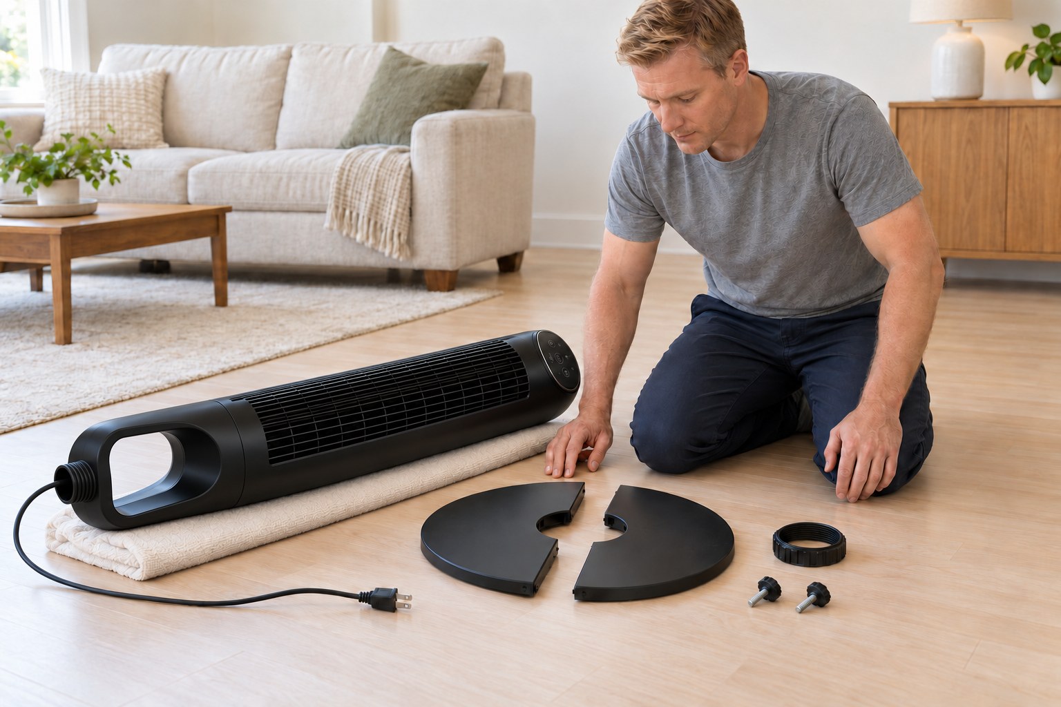
Read the model and electrical label and use the matching US HYF290B instructions. Keep the fan unplugged. Check the housing, grille, attached cord and plug for damage, then identify the two base halves, locking nut and two supplied thumb screws. Work on a dry clear floor and support the housing while handling it. Stop for missing or damaged parts; another regional model needs its own guide and suitable supply.
Photorealistic illustration · Waey
2. Join the two base halves
Remove the two thumb screws from the base if fitted and keep them safely together. Align the front and rear base pieces and press them together gently until their joining features snap securely. Check the whole seam and center opening. The base must form one sound piece without a raised joint or crack. Keep the fan housing supported and disconnected; do not force damaged clips or substitute glue for the supplied fixing system.
Photorealistic illustration · Waey
3. Seat the housing in the base
Remove the locking nut from the bottom of the housing and set it aside. Support the housing carefully and pass the disconnected power cord through the center opening of the assembled base. Lower the housing into the base, matching the rear of the housing with the rear of the base. Rotate it gently until seated as shown in the matched assembly diagram. Keep the cord free and never lift the fan by its cord.
Photorealistic illustration · Waey
4. Secure the central locking nut
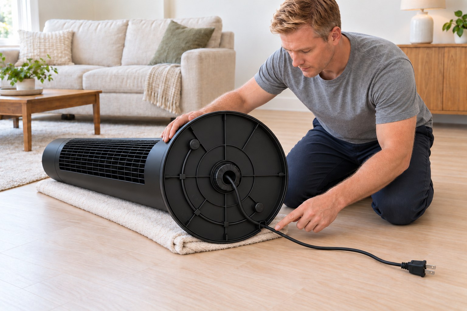
Pass the free plug and cord through the locking nut, then bring the nut up inside the base to the housing thread. Support the fan securely while accessing the underside; keep it disconnected. Engage the thread straight and turn the nut clockwise until fully tightened and the ratcheting described in the manual is heard. Do not use pliers or force a cross-threaded nut. Recheck that the housing sits correctly in the base.
Photorealistic illustration · Waey
5. Route the cord and fit both thumb screws
Gently lay the disconnected fan on its side with the housing supported. Press the cord into the designated guides underneath the base and lead it out through the edge notch shown in the manual. Fit both supplied thumb screws in their base fixing positions. Return the complete fan upright and check that the base rests flat, with no cable trapped underneath and no loose joining seam. Do not run it while lying down.
Photorealistic illustration · Waey
6. Choose a safe floor position
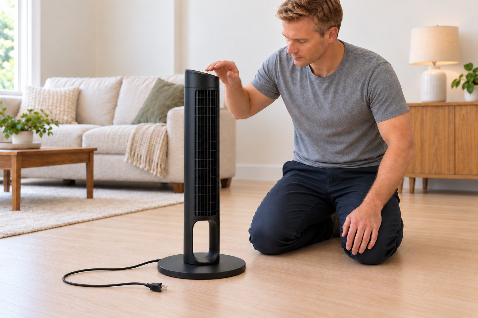
Place the assembled fan upright on a dry level indoor floor with clear inlet and outlet grilles and room for oscillation. Keep it away from water, a window, heat sources and loose curtains. Run the cord in the open away from traffic; do not hide it under rugs or furniture. Use a sound compatible wall outlet directly, without an extension cord, external speed controller or voltage converter. Stop if the plug or outlet is damaged or loose.
Photorealistic illustration · Waey
7. Check speed and oscillation
With the base secure and the fan upright, connect it to the matching supply and press Power on the local control panel. The matched HYF290 starts at Sleep. Press Fan Speed repeatedly to check the available levels, then select a comfortable one. Toggle Oscillation on and off and check that the body moves freely without dragging the cord or rocking the base. Switch off and unplug for scraping, unusual vibration, smell or instability; do not open the housing.
Photorealistic illustration · Waey
8. Check the timer and lighting, then leave safe settings
Use Timer to select one hour and check its indicator; further presses select two, four and eight hours, then the fifth press clears the timer. To verify timed shutoff, allow the full selected period to finish while you remain nearby; the indicator alone only confirms selection. The HYF290 Light button cycles 75%, 50%, 25%, no light, then 100%. Restore your preferred light level and clear any test timer. Switch off and unplug when finished or before moving the fan.
Video demonstrations
Honeywell QuietSet Tower Fan HYF260/HYF290 - How to Assemble
Official manufacturer assembly video visually checked at1:30. Actual frame shows the unplugged cord and locking nut below the open pedestal during attachment to the base. Matched manual governs exact sequence and fixings. Other attempted samples were obscured or failed playback and are not counted. No full audiovisual assessment.
Honeywell Plugged In · English caption track verified; selected visual samples reviewed, speech not fully assessed
Watch on YouTube ↗Honeywell QuietSet Whole Room Tower Fan HYF260/HYF290 - How to Use
Official family-use video visually checked at0:50: three-button remote and caption describing initial Sleep speed. This supports family control context only; this guide uses local HYF290 controls and its matched manual for timer/light functions. No claimed video-verified timer completion or full audiovisual assessment.
Honeywell Plugged In · English caption track verified; selected visual samples reviewed, speech not fully assessed
Watch on YouTube ↗Final checks
Base seam joined; nut and both thumb screws secure; cord guided through notch; fan upright and stable; speed/oscillation checked; test timer cleared; switched off/unplugged before moving.
Where to find supplies
Other regional/HYF260/HYF290E versions need their matched instructions and supply. No fuse servicing, motor opening, grill removal, wall mounting or guaranteed room temperature reduction.
Sources
Manufacturer HYF290B product/support index and assembly FAQ ↗
Three original generated instruction illustrations reviewed individually and in the final JPEG sequence. Disconnected parts preparation is reused for base joining/seating; underside inspection for locking ring/cord guides; upright unplugged context for siting and controls. Actual matched diagrams govern exact molded fittings and button layout. Pictures do not prove electrical rating, ratchet engagement, powered operation or timer completion. Five incorrect mounting/cord/screw/control-layout or missing-pedestal candidates excluded; parts and upright views corrected to the integral open pedestal. Manufacturer documents/video references remain private and were never generation inputs.