
Use a non-contact voltage detector and interpret its limits
Learn a complete preliminary checking sequence: select the detector, check operation before and after use, recognise AC-field indications and avoid dangerous conclusions from silence.
What will you learn?
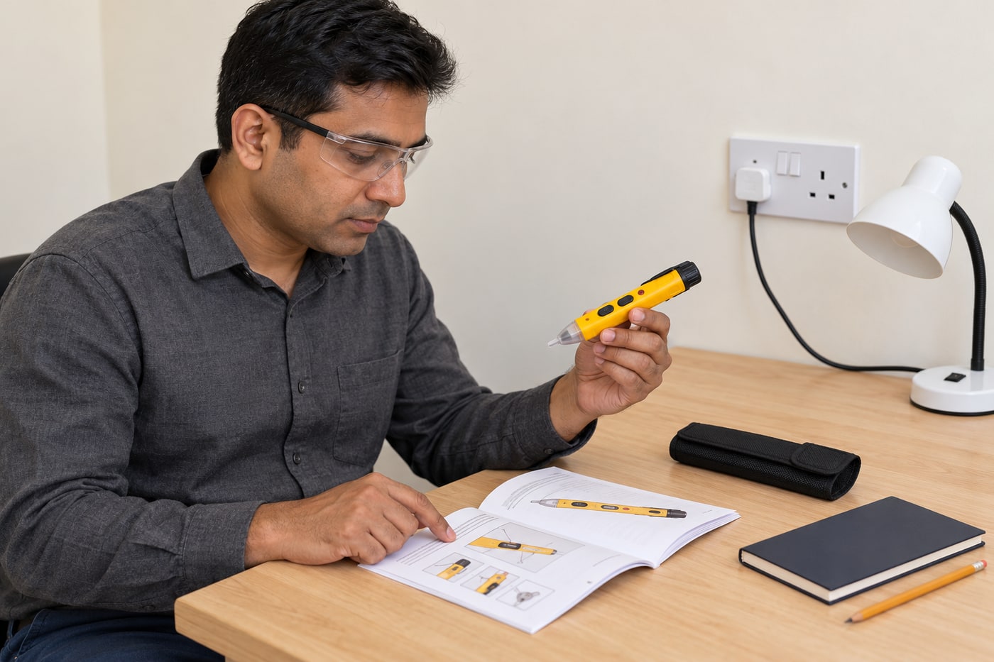
Learn a complete preliminary checking sequence: select the detector, check operation before and after use, recognise AC-field indications and avoid dangerous conclusions from silence. Illustrations show a generic two-button pen and one socket example; actual controls and socket compatibility depend on your model and location.
Tools
- Genuine AC non-contact voltage detector rated for the actual source and setting, with its exact current instructionsSearch Amazon Saudi Arabia ↗
- Approved eye protection and the protective equipment required for the settingSearch Amazon Saudi Arabia ↗
- Pencil or pen for the inspection recordSearch Amazon Saudi Arabia ↗
Materials
- Specified fresh batteries if replacement is neededSearch Amazon Saudi Arabia ↗
- Notebook or inspection recordSearch Amazon Saudi Arabia ↗
Step by step
Photorealistic illustration · Waey
1. Choose the right detector and define what it can establish
A non-contact voltage detector senses the electric field associated with AC voltage; it does not measure current, certify earthing or establish that equipment is safe to touch. Choose a genuine, undamaged instrument whose voltage range, frequency, category and environmental limits suit the intended check, and read its exact manual. This guide covers preliminary checks around intact enclosed equipment only. Check the model and date code against manufacturer recalls. Do not use an unfamiliar pen as permission to open a socket or work on wiring.
Photorealistic illustration · Waey
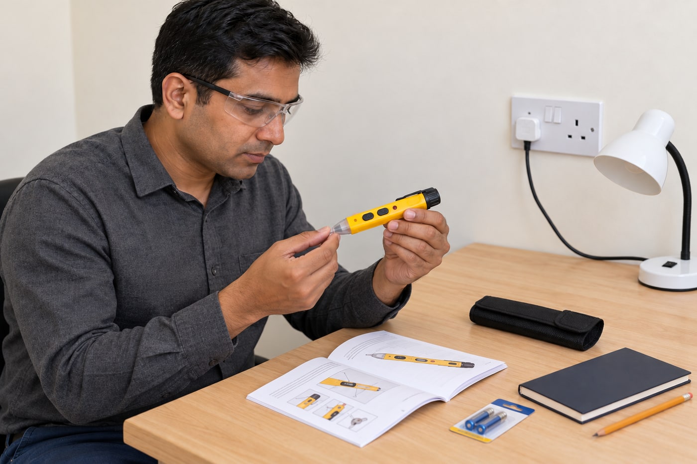
2. Inspect the tool and prepare a dry, enclosed test area
Away from the source, inspect the insulated tip, housing, buttons and battery-cap seal for cracks, contamination or looseness. Fit the specified batteries with the correct polarity when required, then fully close the cap. Use approved eye protection and the protective measures required for the setting. Keep the floor, hands and equipment dry, with good light and no exposed conductors. Damaged, hot, buzzing or scorched sockets are not practice points: stop and arrange electrical assessment without touching or opening them.
Photorealistic illustration · Waey
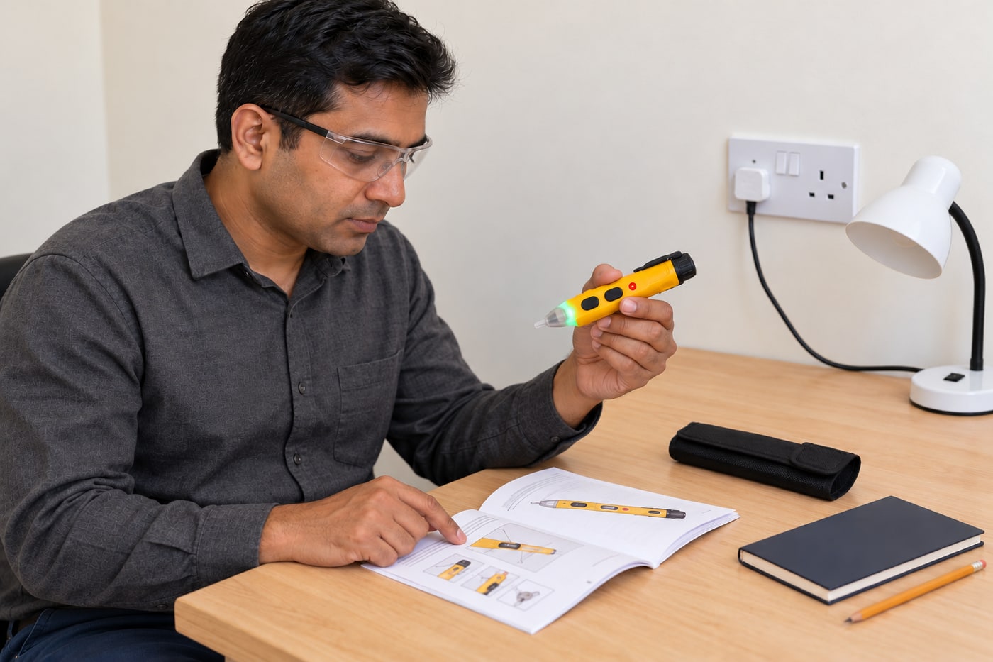
3. Recognise power-on, sensitivity and detection as different signals
Identify the NCV power control, mode indicator and detection tip from the manual; a separate torch is not a voltage test. For example, Klein NCVT3P/NCVT3PEU Mode 1 covers 70–1000 V AC and Mode 2 covers 12–1000 V AC. The manufacturer recommends Mode 1 when the expected voltage exceeds 70 V AC. These are model-specific examples, not universal pen settings. Confirm the selected mode each time because the tool remembers its last mode. A green standby light or successful self-test does not prove the nearby circuit dead.
Photorealistic illustration · Waey
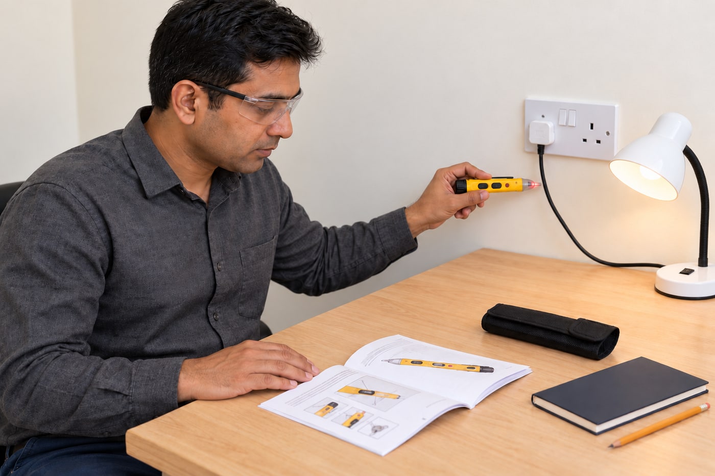
4. Check operation on a suitable known-live source first
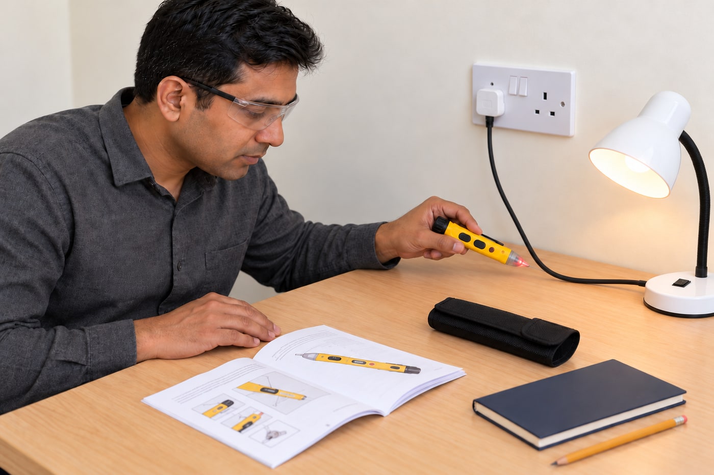
Before the intended check, verify detection at a sound, known-energised source within the tool’s rating, using the manufacturer’s permitted insulated approach. Keep fingers on the designated grip behind the sensing tip. Bring the plastic tip near the accessible exterior of an intact compatible outlet or insulated supply cord and hold it still long enough to read its signals. Never force it through shutters, insert improvised probes or uncover terminals. If that enclosed source does not produce the expected indication reliably, the function check has failed: stop rather than assuming the tool works.
Photorealistic illustration · Waey
5. Make the preliminary check without opening the equipment
Keep the same verified setting and correct grip. Position the sensing tip close to the accessible outer insulation or closed outlet face specified by the manufacturer, without touching damaged insulation or bare metal. Observe the designated detection light and sound, distinguishing them from power-on and torch indicators. A positive signal means an AC electric field is being detected and the equipment must be treated as potentially live. It does not identify a particular conductor’s function, measure amperes or show that an appliance is drawing load current.

Photorealistic illustration · Waey
6. Interpret silence and inconsistent indications correctly
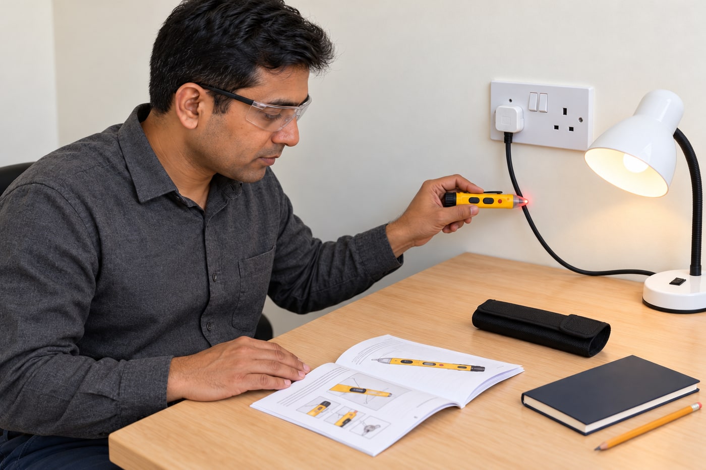
No alarm means the detector has not detected a sufficient field at that position; hazardous voltage may still be present. Shielding, adjacent grounded metal, thick insulation, socket shutters, distance, interference, batteries and the user’s coupling can affect the response. Higher sensitivity can also respond to nearby fields, so it cannot certify which wire is live inside a cable. Do not remove required PPE, touch an earth connection, defeat shutters or strip insulation to force a result. An ambiguous response is a reason to stop and obtain an appropriate competent-person assessment.
Photorealistic illustration · Waey
7. Repeat the known-live function check after use
Return to the same suitable known-live check point immediately after the intended check, maintaining the verified mode and correct approach. Confirm the expected detection indication again. If the tool has switched off automatically, changed mode, developed a low-battery warning or failed to respond, do not rely on the earlier result; correct the tool issue and repeat the complete checking sequence only where safe. Before-and-after function checks test the detector’s operation. They do not transform a non-contact pen into an instrument for proving that an isolated circuit is dead.

Photorealistic illustration · Waey
8. Record a limited conclusion and choose the correct next action
Record the instrument, mode, check location and whether both function checks succeeded, using wording such as “AC field detected” or “no indication; voltage not ruled out.” Do not label a socket safe, assign L/N/PE or authorise work from the pen result. HSE GS38 distinguishes live-identification sticks from the suitable contact instruments used by competent people for proving dead after safe isolation; local requirements also apply. Keep covers closed and arrange that separate process if wiring work is needed. Power off and store the detector according to its manual.
Video demonstrations
Dual-Range Non-Contact Voltage Testers (NCVT-2P and NCVT-3P)
Manufacturer demonstration of dual-range controls and indicators on NCVT2P/NCVT3P. Follow your exact regional model’s manual; the torch and green standby indicator do not establish absence of hazardous voltage.
Klein Tools · English
Watch on YouTube ↗How to use Non-Contact Voltage Detectors
Fluke demonstrates non-contact AC-field detection with different models and ranges. Use this as a comparison of technique and limitations, not as interchangeable controls or permission to approach exposed terminals. This guide keeps covers closed; no pen result proves dead.
Fluke Corporation · English
Watch on YouTube ↗Final checks
Correct model/rating/mode; intact housing; dry enclosed setting; successful known-live checks before and after; no negative-result safety inference; no opened equipment.
Sources
Klein current NCVT3P instructions, Rev11/24 E ↗
Klein current NCVT3PEU instructions, Rev12/25 A ↗
Fluke: NCV operating principle and model-dependent ranges ↗
HSE GS38: live identification versus proving dead ↗
Klein manufacturer recall index: check exact model/date code ↗