
Join isolated wires with a WAGO221-2411: qualified-user bench exercise
For electrically qualified users: prepare and join two isolated solid copper practice wires, inspect the inline connection and verify continuity without power.
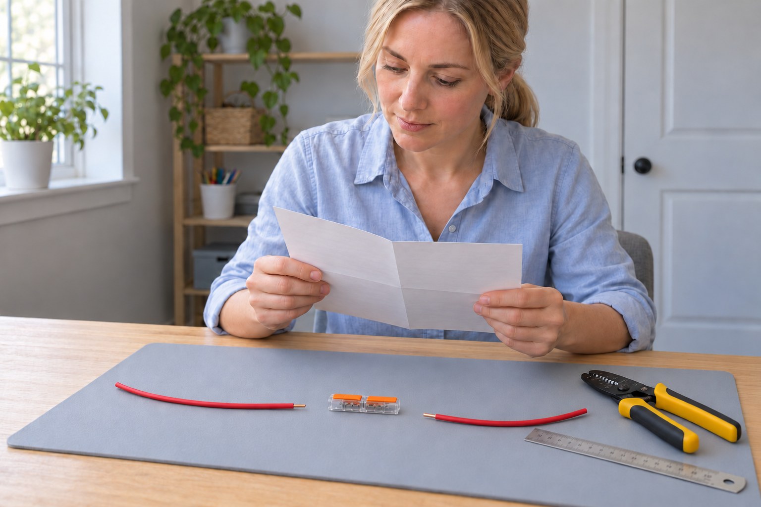
What will you learn?
For electrically qualified users: prepare and join two isolated solid copper practice wires, inspect the inline connection and verify continuity without power.
Tools
- Correctly sized wire stripper and side cuttersSearch Amazon South Africa ↗
- Millimetre rule and actual connector strip gaugeSearch Amazon South Africa ↗
- Fluke101 with intact compatible leads/manualSearch Amazon South Africa ↗
Materials
- Genuine WAGO221-2411 with current matching instructionsSearch Amazon South Africa ↗
- Two short completely disconnected clean1.0mm²solid copper practice wiresSearch Amazon South Africa ↗
- Label for recording practice resultSearch Amazon South Africa ↗
Step by step
Photorealistic illustration · Waey
1. Confirm the qualified-user bench scope
WAGO specifies electrically qualified users for installing, testing and operating these connectors. This exercise is for those users on a completely isolated bench, with no connection to equipment or power. Confirm genuine 221-2411 on the connector and packaging: it has one straight-through electrical path with entries at opposite ends, not two isolated poles. Select two clean 1.0 mm² solid copper practice wires and the matching current product instructions. Do not proceed with unidentified parts or conductors.
Photorealistic illustration · Waey
2. Prepare the isolated practice wires
Inspect the connector for cracks, dirt or damaged levers and replace it if defective. Cut away damaged wire ends and use a correctly sized stripper to remove 11 mm of insulation at each joining end, checking against the real strip-length gauge. Keep the copper clean and unnotched; do not solder-tin it or add ferrules for this solid-wire exercise. Prepare the remote ends only as needed for the isolated meter check, and keep all bare ends away from other conductors.
Photorealistic illustration · Waey
3. Open the first lever and seat the wire
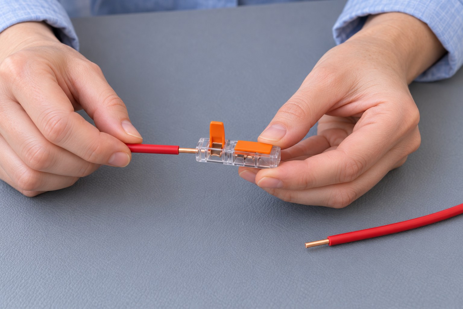
Hold the connector securely and lift the lever for one end fully upright to open its clamp. Insert one prepared conductor straight through that end’s wire entry until it reaches the internal stop. Use the transparent housing to check its position. Do not push through a test opening, force insulation into the clamp or insert two wires into one entry. If the end bends or fails to reach the stop, withdraw it with the clamp open and correct the preparation.
Photorealistic illustration · Waey
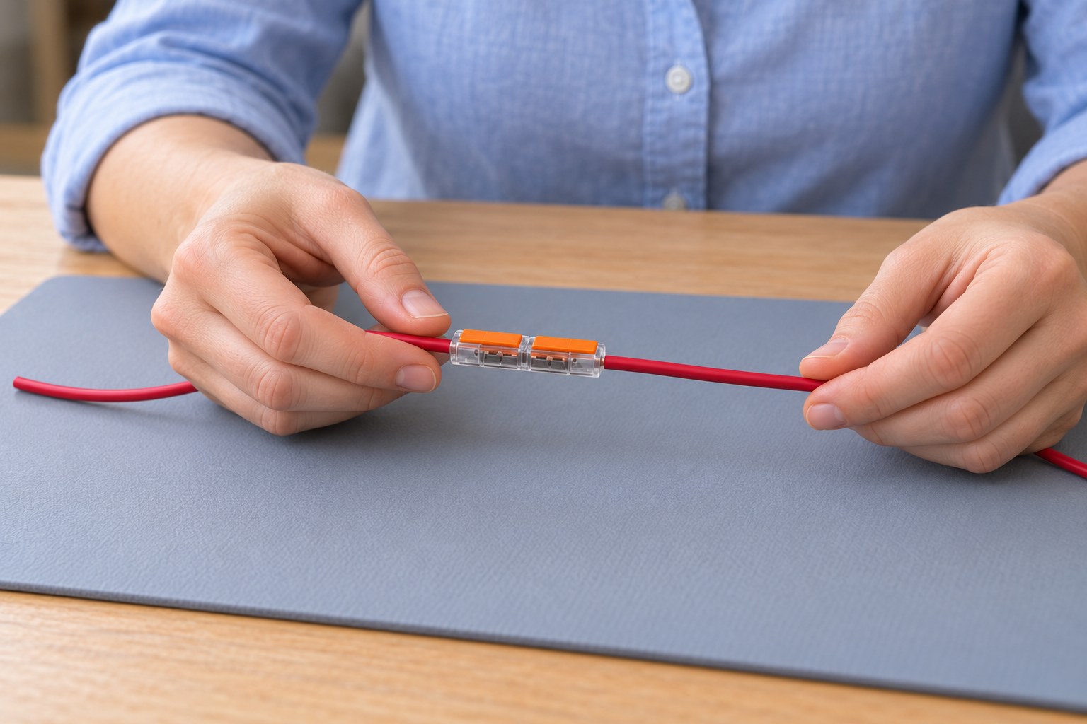
4. Close the first clamp and join the other end
Push the first lever fully down until it lies flush with the housing. Open the opposite lever, insert the second prepared conductor from the opposite end to its stop, and close that lever flush as well. The wires now share one electrical path. Inspect both entries: the copper should be inside the housing, the insulation should approach each entry, and neither joint should show exposed copper outside the connector. Reopen and correct any unsuitable strip length or seating.
Photorealistic illustration · Waey
5. Inspect and check each wire separately
Check the transparent body from more than one angle for full insertion, clean copper and both closed levers. Support the connector and give each wire a separate gentle pull to check that it remains held; avoid twisting, violent pulls or bending the wire at the entry. If a wire moves out or a lever will not close correctly, open that clamp and rework the end. Replace damaged parts. This handling check does not establish a rated pull force or provide strain relief.
Photorealistic illustration · Waey
6. Check continuity without applying power
Keep both wires disconnected from every power source. Set the matched Fluke 101 to resistance, then press its yellow button once for continuity, using black in COM and red in the voltage/resistance input. Confirm open and touching-probe controls, then touch one probe to each remote bare wire end. Expect a steady low reading close to the touching-probe baseline; a beep alone, which occurs below 70 ohms on this meter, does not certify a sound splice. Resolve open, high or unstable readings and repeat the controls.
Photorealistic illustration · Waey
7. Correct faults and finish the practice safely
Before reworking, remove the meter probes and keep the assembly unpowered. Raise the relevant lever fully, withdraw the conductor and inspect it; trim and re-strip a damaged end, or replace a damaged connector. Repeat seating and the checks until the practice joint is satisfactory. Record the connector, conductor and test result. For storage, open both levers, remove the practice wires and put the parts away separately. A real installation also needs its required design, enclosure, routing and strain relief; this exercise does not commission one.
Video demonstrations
WAGO221 Inline Splicing Connector - How To Use!
Official actual0:45 shows matched inline connector with opposite wire entries and both levers closed. Useful for orientation and visible housing, not proof of the selected wire size, strip length, contact quality or ratings. Generic221family0.14–6mm²description is not transferred to221-2411: exact datasheet governs. Additional1:20samplefailed, no claim. No full audiovisual review.
WAGO UK & Ireland · English automatic caption track listed; full speech not assessed
Watch on YouTube ↗221 Series Inline Lever Connector Benefits
Official actual0:35 shows opposed raised levers on inline2411geometry;1:50shows a wire/connector handling context.1:05mounting-carrier presentation is excluded from this bench method. Useful open/closed orientation reference; not pull-force, maintenance-free installation, conductor rating or strain-relief proof. Follow actual manufacturer qualified-user requirement and matched wire/strip instructions. No full audiovisual review.
WAGO UK & Ireland · Indonesian/Portuguese automatic caption tracks listed; spoken language not fully assessed
Watch on YouTube ↗Final checks
11mmjoin ends, sound copper, full seating, levers flush, no external copper at joints, separate gentle retention checks and reliable low isolated continuity; no load/rating/strain-relief certification.
Where to find supplies
Exact221-2411, one copper solid1.0mm²wire per opposed entry, isolated qualified-user bench exercise only. No221-412branch, two-wire-one-entry, solder-tinning, aluminium, ferrule substitute, mains installation or accessory strain-relief claim. Other conductor branches and actual installation design require their own matched documentation.
Sources
WAGO current exact221-2411 product page ↗
WAGO-authored221-2411 datasheet version17March2025, distributor-hosted exact6-page document ↗
WAGO-authored operating/safety user note0888-9999/0100-0101 dated23October2024, distributor-hosted ↗
Fluke101 matched continuity/manual safety, actualfigures previously reviewed ↗
Three original generated contexts individually reviewed and checked as final JPEG sequence across seven steps: corrected two-lever preparation, open-clamp single solid-wire insertion and closed opposed-entry joint/qualitative retention context. Same blonde woman/pale-blue shirt/dry grey mat/red solid copper practice wires. Initial ambiguous four-button connector candidate rejected. Actual221-2411geometry/markings,1.0mm²wire,11mmstrip length, full insertion, absence of power, remote bare ends, continuity controls/readings, pull force, qualifications and installation compliance require real documentation and physical checks; not proved by illustrations. Meter test is not pictured. No manufacturer diagrams or video frames were generation inputs.